234 Results
View results:
Sort by:
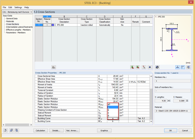
You can adjust the buckling curve of a cross-section in RF-/STEEL EC3, if necessary. This can be done in Window 1.3, Cross‑Sections.

This article describes and explains the influence of bending stiffness of cables on their internal forces. Furthermore, the text provides information on how this influence can be reduced.

Lateral-Torsional Buckling (LTB) is a phenomenon that occurs when a beam or structural member is subjected to bending and the compression flange is not sufficiently supported laterally. This leads to a combination of lateral displacement and twisting. It is a critical consideration in the design of structural elements, especially in slender beams and girders.

In this article, you will learn how to model and design cable structures in RFEM 6 or RSTAB 9.

The national parameters of EN 1992‑1‑1 for each country can be exported from RF‑/CONCRETE, RF‑/CONCRETE Columns, and RF‑/FOUNDATION Pro. To do this, there are interfaces with MS Excel, OpenOffice, and CSV. By exporting the national parameters, you can edit them in (for example) MS Excel, and display possible differences between the individual National Annexes clearly (see the image).
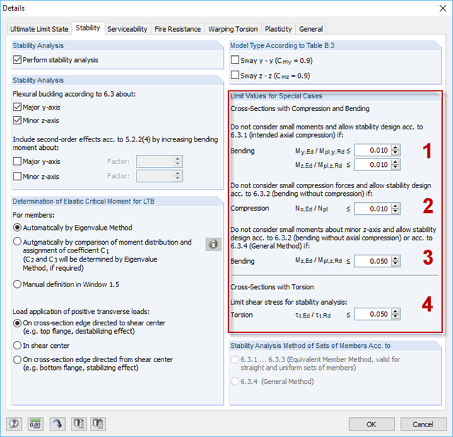
For situations where no design is available, RF-/STEEL EC3 provides the option to neglect the respective internal forces. Examples of such situations are: bending and compression on angle sections, multi-axial bending for the design according to the General Method, torsion.

When calculating foundations according to EC 7 or EC 2, different foundation types or sizes are usually used in one object. However, boundary conditions like the soil parameters, the materials for foundations, concrete covers, and the load combinations selected for design remain the same for all foundations, as a rule.

In RF-/FOUNDATION Pro, a graphical display of the result details is available. To see them, go to Window 2.2 Governing Design Criteria after the calculation. In the interactive graphic of this window, individual design-relevant values can be displayed for each design performed.

Various optimizations are available with program version x.06.1103. The RF-/FOUNDATION Pro add-on module has also been subjected to further development.

The automatic surface reinforcement design process determines a surface reinforcement that covers the required amount of reinforcement.
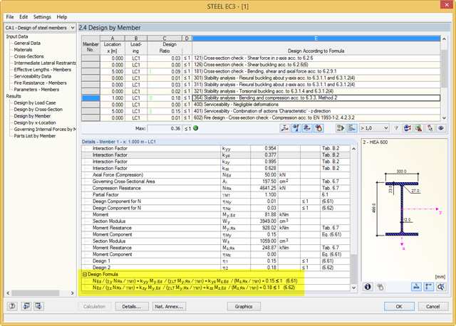
RF-/STEEL EC3 performs the classification, cross‑section designs, serviceability limit state designs, and fire resistance designs of members. For each design, the program shows a result table with the relevant values and classification numbers, including information regarding the respective standard clause. In order to identify the conjunction of various standards easily, there is a final design equation, including all terms, at the end of the table.

The determined values for the influence ordinates are displayed as decimal numbers with up to six decimal places by default. This is usually sufficient for the influence lines of internal forces.

For structural reasons, shear connections usually include fin plates or flange angles. Main and secondary beams arranged on the top edge require notching or long fin plates. Hinged end plate connections are often welded to the web.

For foundation design, it is necessary to define the relevant loads for the respective design situations (STR, GEO, UPL, EQU).

In January 2015, DIN Committee NA 005‑08‑23 Steel Bridges applied the introduction of a modification in equation 10.5 of DIN EN 1993‑1‑5. This involves the interaction of longitudinal and transverse pressure in a buckling analysis. Now, the interaction equation provides for auxiliary factor V, which is calculated from the reduction factors of the longitudinal and transverse stresses.
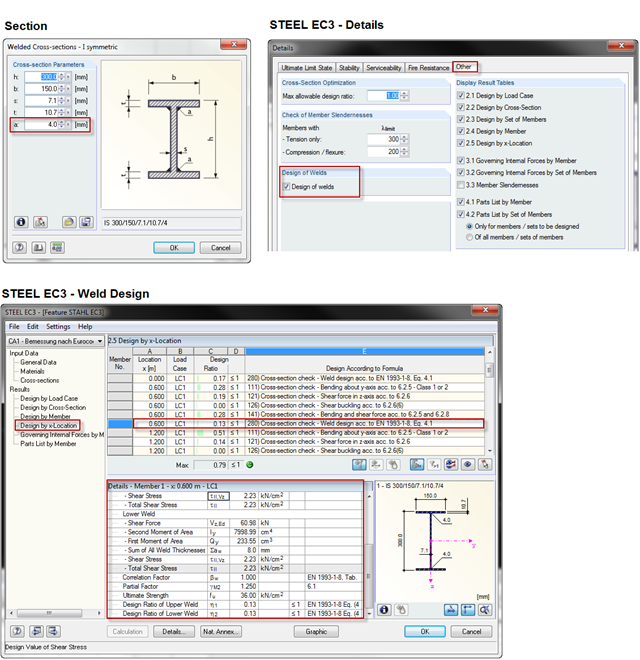
When using a welded profile, weld seam verification can also be carried out in RF-/STEEL EC3 as part of the design. The program performs the typical designs according to EN 1993‑1‑8.

In RF‑/FOUNDATION Pro, the available reinforcing steel diameters can be adjusted by the user. The adjustment of the available rebar diameters works similarly to the same function in the RF‑/CONCRETE (Members) and RF‑/CONCRETE Columns add‑on modules.

The classification of cross-sections according to EN 1993‑1‑1 and EN 1993‑1‑5 can be carried out automatically in the RF‑/STEEL EC3 add-on module. The maximum c/t ratios are specified in the standard for straight cross-section parts. There are no normative specifications for curved cross-section parts; therefore, the cross-section classification cannot be performed for these cross-section parts.
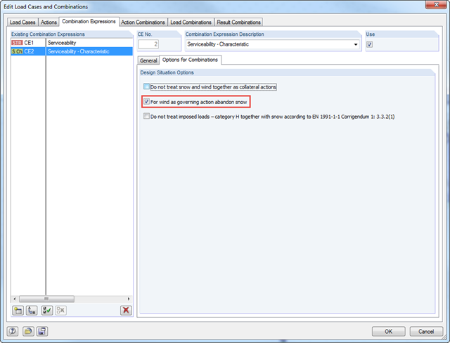
According to DIN EN 1990/NA:2010‑12 - NDP to A.1.2.1(1) Comment 2, it is possible to neglect the combination of snow as a collateral action in cases of wind/snow combination with wind as the leading action in wind zones III and IV.
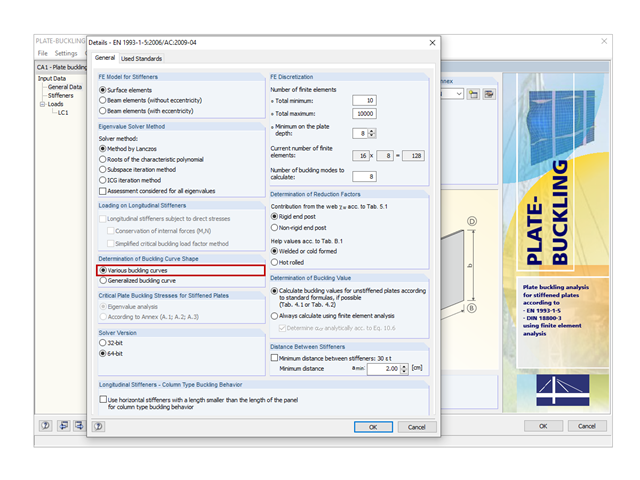
In PLATE‑BUCKLING 8, two options in the detail settings can be used to calculate the reduction factors of plate buckling.